Review: In-Class Question
What kinds of databases are there?

Review: Database Types

Review: In-class Question
What are relational databases?

Recap: Relational Databases
RDBMS have been in use since the early 1980s and are based on the relational (= table-oriented) data model
The schema of a table (= relation schema) is defined by the table name and a fixed set of attributes (= columns) with corresponding data types
Since data are organized in tables, they are highly structured with a structure defined by the table (normalization)
The standard language for creating/modifying/deleting is SQL
Popular systems: Oracle, MySQL, Microsoft SQL Server, PostgreSQL, IBM Db2
Review: Lecture Hall Question
What types of keys are there in relational databases?

Recap: Key References
Municipalities Table
| MunicipalityID | Name | Population |
|---|---|---|
| 1 | Dummerstorf | 7,329 |
| 2 | Graal-Müritz | 4,278 |
| 3 | Sanitz | 5,831 |
Primary key: MunicipalityID
Buildings Table
| BuildingID | Building Type | MunicipalityID |
|---|---|---|
| 5000 | Gas Station | 2 |
| 5001 | Hotel | 1 |
| 5002 | Church | 2 |
Foreign key: MunicipalityID
Process

Database Design Process
The traditional design process resembles the waterfall model used in software design.
- Requirements analysis: What requirements and use cases does the database need to support?
- Conceptual design: High-level design in the ER diagram with entities, attributes, and relationships
- Logical design: Detailed design of the concrete database schema for a specific DBMS
- Physical design: Primary indexes and secondary indexes to optimize access
- Implementation: Creating the database with SQL
- Maintenance: Using the database
Entity-Relationship Model - Introduction
- Entity-Relationship models design the data model of a database
- They specify: what, how, and with which relationships data is stored
- Often found in software documentation and procurement specifications
- Developed in 1976 by Peter Chen: "The Entity-Relationship Model"
- Various variants of ER diagrams exist
ER Model - Basic Concepts
Core Concepts:
Entity Type: Class of objects (Example: Point, Line, Polygon)
Entity: A single identifiable object (Example: A single point)
Additional Components:
Attributes: Properties of an entity (Example: the x and y coordinates of a point)
Relationship: Relationships between entities (Example: Point (0,0) "belongs_to" Line 1)
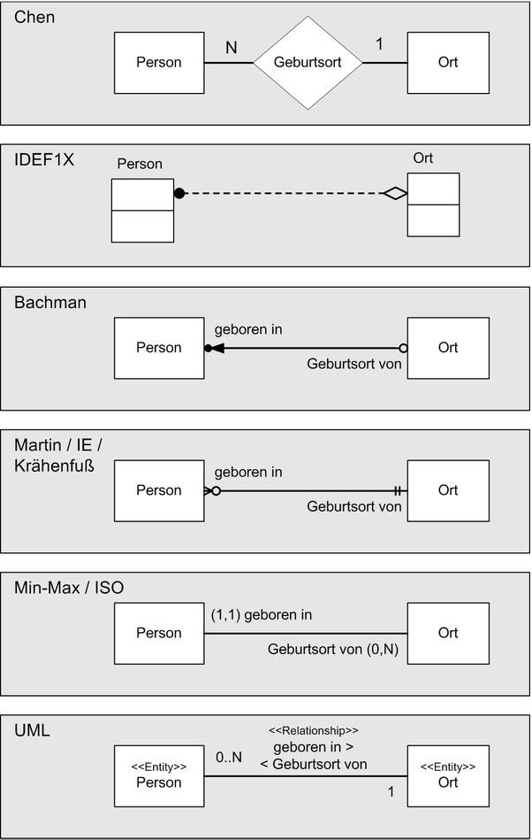
Diagram Types — Different Notations
Historical development:
- Chen notation (Peter Chen, 1976)
- IDEF1X (U.S. government standard, 1985)
- Bachman notation (Charles Bachman, 1969)
- Crow's Foot notation (Gordon Everest, 1976)
- (min, max) notation (Jean-Raymond Abrial, 1974)
Modern approaches:
UML as an ISO standard (replacement for ER diagrams)
Terminology Differences
| Object Orientation | Relational Database | ER Diagrams |
|---|---|---|
| Object Instance | Data Tuple | Entity |
| Classes | Relations | Entity Type |
| Class Definition | Relation Schema | Entity-Relationship Model |
| Attribute | Attribute | Attribute |
| Association | Foreign Key | Relations |
| Multiplicities | - | Cardinalities |
OOP vs Relational Databases - Comparison
| Feature | Object-Oriented | Relational Databases |
|---|---|---|
| Modeling | ✅ as objects | ✅ as relations |
| Attributes | ✅ | ✅ |
| Methods | ✅ | ❌ |
| Inheritance | ✅ | ❌ |
| Polymorphism | ✅ | ❌ |
| Generalization | ✅ | ❌ |
| Aggregation | ✅ | ❌ |
| Encapsulation | ✅ | ✅ |
Object-Oriented Software Design
In object-oriented software design, a program of objects is modeled:
- Class Definition: How are objects defined in the form of classes?
- Attributes and Methods: What properties and behaviors do they have?
- Inheritance: How do classes build on one another?
- Static Relationships: How do they relate to each other?
- Dynamic Interaction: How do they interact at runtime?
Modeling Language: UML diagrams
Database Design
In database design, an entity-based database is modeled:
- Entity types: How are they defined in the form of tables?
- Attributes: What properties do entities have as columns?
- Static relationships: How do they relate to each other?
Modeling language: Entity-Relationship diagrams
UML for ER Diagrams - Special Features
Annotate classes with
<<Entity>>Attributes as class attributes with data types
PK designates the primary key
Foreign keys as associations
Reading direction:
<<or>>Numbers indicate cardinality
No methods!
Cardinalities (Multiplicities)
| Cardinality | Example | ER Diagram |
| 1 to 1 | The relationships are represented by foreign keys in the entity from which the relationship starts, denoted by `>>`. The foreign key is `NOT NULL`, so an entry must ALWAYS be present. | |
| 1 to 0..1 | The relation is represented by a foreign key in the entity. The foreign key is `NULLABLE`, so an entry does not have to be present. | |
| 1 to 0..* | The relation is represented as a new entity with a foreign key. | |
| 1 to 1..* | The relation is represented as a new entity with a foreign key. At least one entry should exist (this is a consistency rule that cannot be enforced by a DBMS alone (there is otherwise a chicken-and-egg problem)). |
From the Conceptual Model to the Logical Model
- Different DBMSs offer different data types
- Complex attributes (lists, dictionaries) cannot be stored directly
- Relationships with multiplicities greater than 1 cannot be stored in a single table with the entity
- Redundant data (e.g., polygon type or addresses) that always have the same values waste storage unnecessarily and are hard to maintain (updates in many places)
- These constraints mean that conceptual data models are often not directly mappable to a database
Normalization
Normalization is an important step in the process of mapping a conceptual data model to a logical and physical data model. Its purpose is to minimize redundancies (storing the same fact multiple times) by:
- complex attributes are moved to new tables
- high-cardinality relationships are moved to new tables
- redundant data (e.g., polygon type) are moved to new tables
Normal Forms
Different normal forms with progressively stricter constraints on the database schema:
- 1st Normal Form: All attribute values are atomic (not complex)
- 2nd Normal Form: Non-key attributes are fully functionally dependent on all primary keys
- 3rd Normal Form: Non-key attributes are functionally dependent only on the primary key
- Boyce-Codd Normal Form: All attributes on which attributes depend are keys
- 4th Normal Form: There are only trivial multivalued dependencies left
- 5th Normal Form: There are no multivalued dependencies that depend on each other
This results in many, highly simplified tables, which can be recombined into larger relations.
Most of the time, only the first three normal forms are relevant in everyday database work.
First Normal Form
- Example: First Normal Form violated
- Error: List
as attribute instead of relation
-- Falsch: Komplexe Attribute
CREATE TABLE Polygon (
    id INT PRIMARY KEY,
    punkte LIST<Punkt>  -- Verletzt 1NF
);
-- Richtig: Atomare Attribute
CREATE TABLE Polygon (
    id INT PRIMARY KEY
);

CREATE TABLE PolygonPunkte (
    polygon_id INT,
    punkt_id INT,
    FOREIGN KEY (polygon_id) REFERENCES Polygon(id),
    FOREIGN KEY (punkt_id) REFERENCES Punkt(id)
);
Second Normal Form
- Example: Second Normal Form violated
- Error: Point not moved to a separate table
-- Wrong: Not fully dependent on the primary key
CREATE TABLE Linie (
    id INT PRIMARY KEY,
    start_x FLOAT,
    start_y FLOAT,
    end_x FLOAT,
    end_y FLOAT
);
-- Correct: Points moved out
CREATE TABLE Punkt (
    id INT PRIMARY KEY,
    x FLOAT,
    y FLOAT
);

CREATE TABLE Linie (
    id INT PRIMARY KEY,
    start_punkt_id INT NOT NULL,
    end_punkt_id INT NOT NULL,
    FOREIGN KEY (start_punkt_id) REFERENCES Punkt(id),
    FOREIGN KEY (end_punkt_id) REFERENCES Punkt(id)
);
Third Normal Form
- Example: Third Normal Form violation
- Error: PolygonTyp is dependent on Polygon
-- Incorrect: Transitive dependency
CREATE TABLE Polygon (
    id INT PRIMARY KEY,
    typ_name VARCHAR(50),
    typ_beschreibung VARCHAR(200)
);
-- Correct: PolygonTyp moved to a separate table
CREATE TABLE PolygonTyp (
    id INT PRIMARY KEY,
    name VARCHAR(50),
    beschreibung VARCHAR(200)
);

CREATE TABLE Polygon (
    id INT PRIMARY KEY,
    typ_id INT,
    FOREIGN KEY (typ_id) REFERENCES PolygonTyp(id)
);
Cardinalities (Multiplicities)
Cardinalities are represented differently:
- one-to-one: The relation is represented with a foreign key in the entity. The foreign key must not be NULL
- one-to-zero-or-one: The relation is represented with a foreign key in the entity. The foreign key may be NULL
- one-to-zero-or-more: The relation is represented as a new entity with foreign keys
- one-to-one-or-more: The relation is represented as a new entity with foreign keys. At least one entry should exist
Lecture hall question
Which tables do we need for our geometry example?
Lecture Hall Question
By normalization we obtain five tables:
Point: Has the attributes x and y coordinates, data type float
Line: The start and end points are foreign keys that are non-null because there is a one-to-one relation
Polygon: A table with a primary key (PK) and foreign key (FK) to the polygon types; the points are external
PolygonType: A table of the redundant polygon types with name (triangle, quadrilateral, etc.) and PK
PolygonPoints: A table that for each polygon lists the associated point FKs, since there was a 3..* relation
For all five we need a primary key (Always Not Null)
Lesson Learned

Lessons Learned - Procrastination & Exam Planning

- People tend to estimate the time for exam preparation optimistically
- When preparing right before the exam, you realize you need more time -> panic
- You go into the exam in a panic -> bad karma
Lessons Learned - Exam Planning & Time Management

- Pro: You leverage your subconscious to work on it
- Pro: Through the planning and information phase you can better estimate the effort involved
- Con: You can still misjudge
Lessons Learned - Exam Planning & Time Management
First estimate the effort and only then look at the date (don't plan based on how much time you have, but on how much time you need)
| Subject | Exam Type | Content | Study Effort | Date |
|---|---|---|---|---|
| Mathematics | Written | 100% exercises | 2+1 days | |
| Technical Mechanics | Written | 80% exercises / 20% learning | 4+1 days | |
| Computer Science | Written | 50% exercises / 50% learning | 3+1 days | |
| Construction Chemistry | Written | 40% exercises / 60% learning | 3+2 days | |
| Construction Materials | Written | 100% learning | 2+1 days |